1. Deep Penetration Radar. Exploration of Geological Substructures.
Experimental data and numerical simulation.
A.I. Berkut, V.V. Kopeikin, P.A. Morozov, L.M. Krinitsky, Ulyantsev N.A.(VNIISMI Company).
A.V. Popov, I.V. Prokopovich (IZMIRAN).
Conventional GPRs are not widely used for geological exploration. Due to the typically low transmitter power of conventional GPRs, the “sounding depth” in light-textured soils is limited to the top 10 meters. In exploration, these shallow depths are of little interest to geologists.
When developing the "Loza" deep penetration radar, great efforts were taken to make the device's sounding depth attractive for geologists and geophysicists. Loza’s deep penetration radar has the following characteristics; ultrahigh power, signal energy concentration in the low-frequency spectrum area, large dynamic range of reflected signal recording [1], enabling the GPR to be applied in the exploration of subsurface structures to depths of 100-150 meters in heavy-textured low-resistivity soils and up to 200-300 meters in high-resistivity rocks.
Such record sounding depths are achieved through the implementation of new circuit designs and principles:
- The "Loza" GPR is equipped with transmitters whose peak power exceeds the power of transmitters of conventional GPRs by 10,000 – 100,000 times. Achieving such transmitter powers became possible after shifting from a transistor circuit to the pulse generation at high-voltage spark gaps. The "Loza" GPR is equipped with transmitters of 5, 10, 21 kV impulse voltage. 50 and 100 kV transmitters are subject to experimental tests.
- The "Loza" GPR is equipped with low-frequency resistively-loaded antennas (5-25 MHz) allowing them to fulfill the capabilities of super high-power transmitters to the full extent. The antennas are constructed according to the Wu-King scheme with a distributed resistive load. Additional artificial dissipation provides generation of the short, aperiodic pulse, which is best suited for GPR sounding.
- A hardware-software algorithm is used in the "Loza" GPR performing the function of the recorded signal digitization with a dynamic range of up to 120 dB.
- To achieve large sounding depths, the maximum energy of the sounding signal is shifted in the "Loza" GPR to lower frequencies within the frequency band of the 1-50 MHz GPR receiver.
The sounding signal attenuation is essentially dependent on frequency. The lower the frequency is, the less the signal attenuation under the same conditions is. The "Loza" GPRs are series-equipped with 50 MHz antennas (3 meters long), 25 MHz (6 meters long), 15 MHz (10 meters long), 10 MHz (15 meters long). - To achieve record results in depth of sensing in georadar, the effect of focusing radiation towards a more "electrically dense" medium is also used. Only when placing the GPR antennas on the surface (boundary) where the two media are separated, the radiation pattern is formed, oriented towards the medium with a large dielectric permittivity. According to theoretical estimates [3, 4], the electromagnetic signal energy emitted into the lower hemisphere (in the ground) is by n2 times more than emitted upwards (into the air), (where n is the refractive index). The maximum direction of the GPR radiation diagram also depends on the properties of the medium. The higher the dielectric permittivity of the medium, the smaller the angle; and the sounding signal is radiated more focused [1].
All of the above principles for increasing the depth of GPR exploration are implemented in hardware and methodically in modern "Loza" GPR models.
Let us highlight two more questions which often arise when acquainting with the "Loza" GPR characteristics.
Question 1.Many geophysicists who apply GPR in their studies are convinced that the GPR cannot probe to a depth of more than a few meters. Such depth estimate is quite correct, but it shall be clarified that this estimate is made for GPRs constructed according to the classic scheme, operating with transmitters of 50-100 W power in the frequency range of 100-500 MHz. The "Loza" GPR has fundamentally different characteristics. "Loza" operates with 10,000 – 100,000 times more powerful transmitters, and the frequency band of the "Loza" receiver is 1-50 MHz.
The sounding signal attenuation is essentially dependent on frequency. The higher the frequency is, the higher the signal attenuation is. According to theoretical and experimental data, the characteristic curve looks like this:
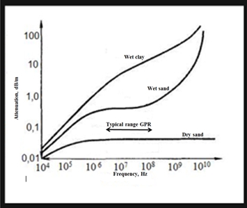
Fig. 1. Dependence of the sounding signal attenuation on frequency.
In the frequency range of conventional GPRs, attenuation can actually be 5-10 and even 20 dB/m for wet clay. This renders the deep GPR sounding impossible. At frequencies below 15-20 MHz, the signal attenuation can be much less than 1 dB/m.
The depth estimate for the "Loza" GPR is as follows:
The GPR potential is determined by the formula:
P = 20•lg(U1/U0)
where: U1 – peak voltage of the transmitter (21•103 V in this case),
U0 - receiver sensitivity, (~10•10-3 V in this case).The device potential shall be:
P = 20•lg (21•105) = 126 dB
At attenuation of approx. 0.3–0.4 dB/m, we get a depth estimate of ~ 400 meters. The resulting estimate must be divided by 2, since the GPR sounding signal passes a double path: from the surface to the reflecting boundary and back. As a result, an estimate of the maximum sounding depth of a GPR with a peak voltage of 21 kV at 15-20 MHz will be ~ 200 meters.
Question 2.The second question is directly related to the first one: Are the transmitters of such great power safe for humans?
The hazard of the danger or non-hazard of such a high voltage can be illustrated by the example of a spark plug in a modern gasoline car engine. The spark plug is just the same spark gap. The ignition distributor delivers a voltage of up to 25,000 volts to the spark plug in the proper car engine cycle. The signal from the "Loza" GPR transmitter is similar in its characteristics to the signal from the car ignition system. There were situations when we used the car ignition system for work in long-distance expeditions in cases of the transmitter malfunctioning. The "Loza" GPR transmitter is as safe as the car ignition system. They work into a load with very high resistance. The pulse voltage is very high, and the electric current flowing during the discharge is microscopically low. This fact is confirmed by certified laboratories, who have issued Loza the necessary certificates.
The "Loza" deep penetration radar capabilities can be illustrated by the results of certain geophysical studies. Figures 5-9 show the examples of radargrams, in which the geological structures and objects surveyed are presented quite recognizable without any processing.
The amplitude and phase values on the radargrams are presented by a palette of colors. It is conventionally accepted that the maximum amplitude values of the positive polarization are indicated by red hues, and the maximum amplitude values of the negative polarization are indicated by blue and dark blue hues. The amplitude values in the range of "zero" values are indicated by yellow hues. All intermediate values of the amplitude are indicated in color hues according to the color palette (256 levels). Variations of the conventional color on the radargrams enable visual presentation of the entire dynamic range of the amplitudes (more than 120 dB) and phases of the sounding signal. Only the boundaries of different hues zones and the order of color change have geophysical meaning.
Analysis of low-frequency signals on waveforms shows that there is a connection between the amplitude and phase of these signals and the integral characteristics of the dielectric permittivity (?) and conductivity (?) of deep geological horizons.
We are currently developing the improvement of the analysis methods and interpretation of deep penetration radar data in two directions. The first option is related to the heuristic approach, which is implemented by accumulating the experience of comparative analysis of low-frequency GPR data and the results of geological check drilling [2, 3, 4]. The interpretation experience allows marking the zones of increased or decreased values of the dielectric permittivity (?) and conductivity (?) accurately by GPR data. These zones correspond to certain geological structures, which are contrasting in terms of dielectric permittivity and conductivity (Figures 5-9).
The second direction of the development of methods of analysis and interpretation of GPR data is associated with the use of approximate methods for solving the inverse problem. Figure 2 shows the variants of the estimated recovery of changes in depth of environmental parameters (dielectric permittivity) by the experimental GPR data [1, 5].
The GPR profile (Fig. 3) crosses an element of the ancient paleotopography (probably, paleochannel). The paleotopography feature is filled with moisture-saturated soil. This is confirmed by both GPR data (powerful LF signal, polarization "+") and numerical simulation (the dielectric permittivity (?) increases from 10 to 16) (Fig. 2d).
In the following examples (Fig. 3-8) presents the options for geological applications of GPR Loza:
- Study of paleotopography features,
- Study of tectonic dislocations,
- Study of tectonic faults,
- Exploration of kimberlite pipes,
- Groundwater exploration.
All presented results were obtained with the help of "Loza-N" GPR in the expeditions of the VNIISMI Company or "Loza-N" GPR users.
Development of methods for numerical analysis of deep-GPR supported by the RFBR grant No. 18-02-00185.
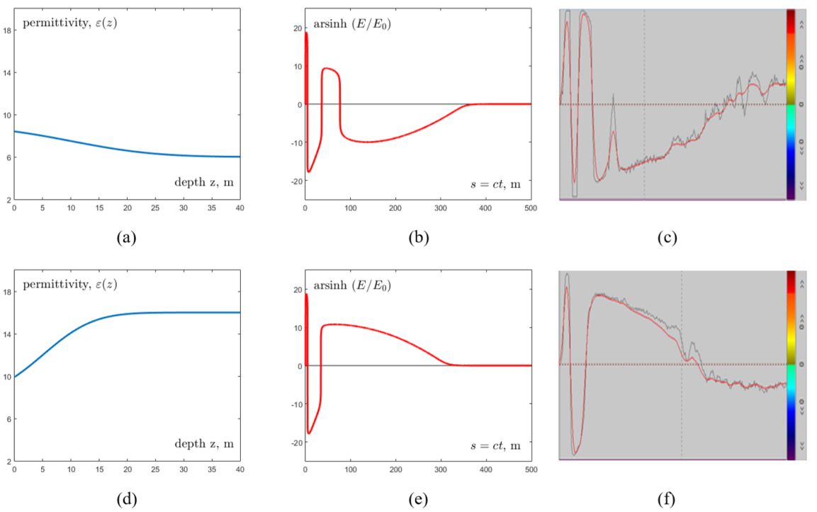
Fig. 2. (а, d) – model vertical distributions of relative dielectric permittivity, (b, e) – received signal in quasi-logarithmic scale; (c, f) – experimental A-scans (1) and (2) from Fig. 5
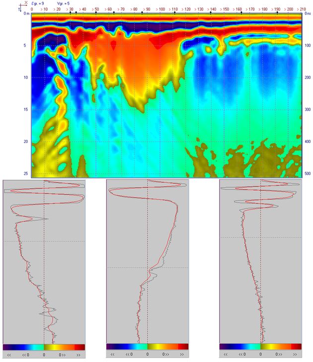
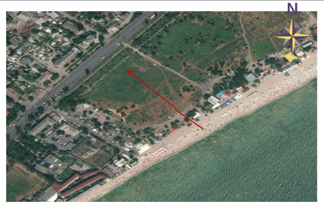
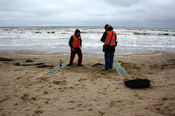
Fig. 3. Radargram of the paleotopography feature, Google-snapshot and the work site photo, Odessa, 2017.
(1, 2, 3) – A-scans at the characteristic points of the profile.

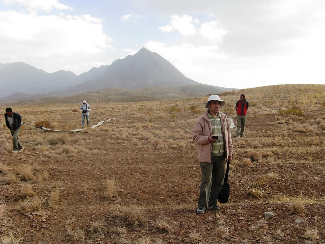
Fig. 4. Radargram of the tectonic block gap, rift and the work site photo.
Iran. 2012
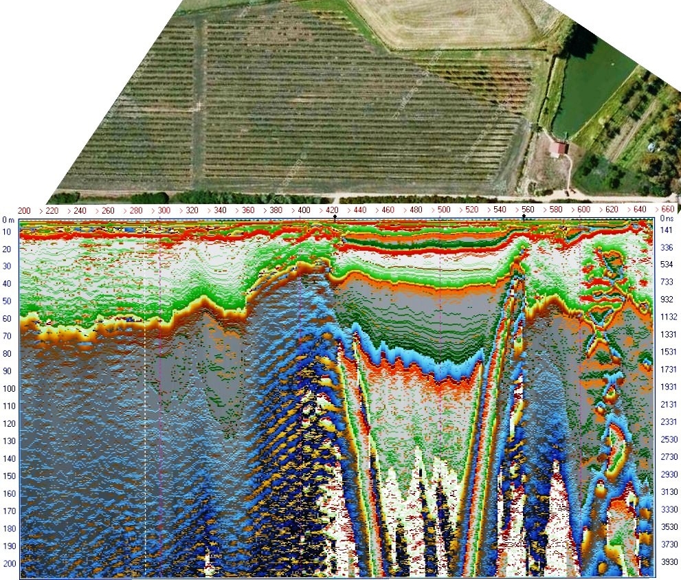
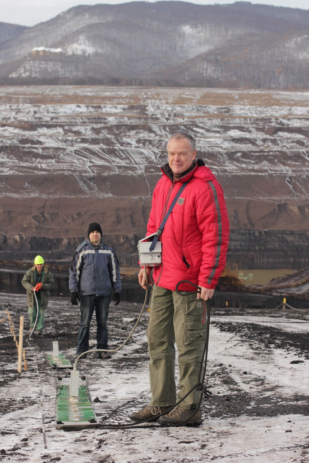
Fig. 5. Radargram of the tectonic gap (rift-valley type) and the work site photo.
KDANICE, Czech Republic, 2014

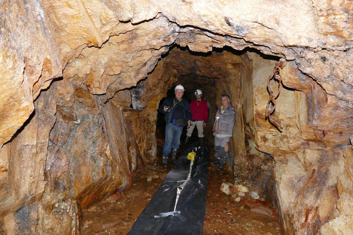
Fig. 6. Radargram of a tectonic fault. The adit in Lobo Mountain, a gold ore deposit.
Spain, September 2016.
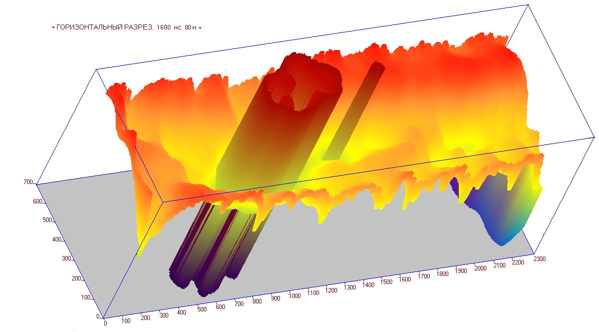

Fig. 7. 3D presentation of the kimberlite pipe reconstructed according to a network of parallel GPR profiles on the 0.7x2.3 km.
Arkhangelsk Oblast, 2014.
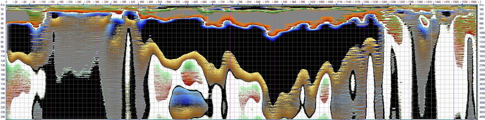
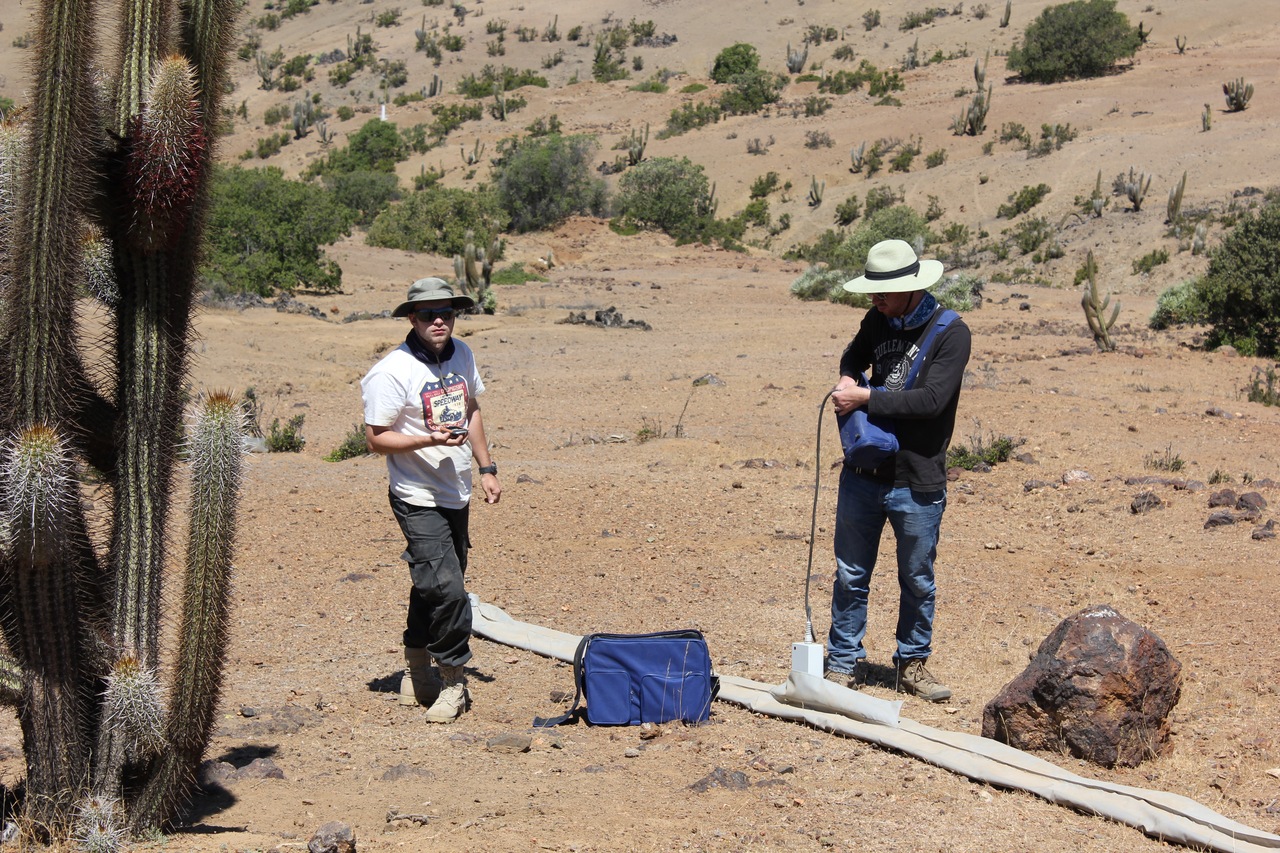
Fig. 8. GPR exploration of groundwater horizons, promising for drilling wells in South America, San Nicolas, Chile.
Literature:
- Berkut A.I., D.E. Edemsky, V.V. Kopeikin, P.A. Morozov, I.V. Prokopovich, A.V. Popov, Deep penetration subsurface radar: hardware, results, interpretation. /Proc. 9th Int. Symp. on Advanced Ground Penetrat. Radar (IWAGPR), PS-2, 3 25, Edinbourgh, UK, 2017.
- Experience of the "Loza" series GPRs use in searching for overlapped copper-gold zones, V.Ya. Pchelka, A.N. Mikhno, E.G. Malchenko, G.G. Freiman, Т.D. Malchenko, "Prospect and protection of mineral resources" 2(43)2012, pp. 82-88.
- Prospects for the application of innovative technologies using super high-power ground-penetrating radars in engineering and field geology, Morozov P.A., Ulyantsev N.A., Borodin V.P., Ingovatov A.P., "Prospect and protection of mineral resources" (geophysics) No. 1, Journal of the Ministry of Natural Resources and Environment of the Russian Federation. Moscow, January 2012, pp. 35-38.
- Low-frequency vertical radar sounding in the practice of geological exploration. V.Ya. Pchelka, A.N. Mikhno, E.G. Malchenko, Т.D. Malchenko, G.G. Freiman, “Earth sciences in Kazakhstan”, (International Geological Congress IGC – 35, South Africa, Report of Kazakhstanian Geologists), pp 430-438, Almaty 2016.
- A.I. Berkut, L.M. Krinitsky V.V. Kopeikin , P.A. Morozov, A.V. Popov, I.V. Prokopovich. Deep Penetration Radar: Hydrogeology and Paleorelief of Underlying Medium. 17th International Conference on Ground Penetrating Radar, Rapperswil, Switzerland, June 18–21, 2018.